Mechanical Engineering Drawing Symbols
Online Library Mechanical Engineering Drawing Symbols Chart easy to overlook the computational and graphics capabilities offered by Microsoft® ExcelTM. The software is nearly ubiquitous and understanding its capabilities is an enormous benefit to engineers in almost any field and at all levels of experience. Block of an engineering drawing. EO 1.4 STATE the purpose of the notes and legend section of an engineering drawing. The ability to read and understand information contained on drawings is essential to perform most engineering-related jobs. Engineering drawings are the industry's means of communicating.
- Mechanical Engineering Drawing Symbols And Their Meanings
- Mechanical Engineering Drawing Symbols And Their Meanings Pdf
- Mechanical Engineering Drawing Symbols Pdf
- See Full List On En.wikipedia.org
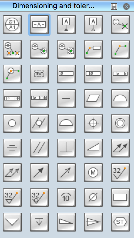
Use these geometric dimensioning and tolerancing (GD&T) shapes to create annotated mechanical drawings.
'Geometric dimensioning and tolerancing (GD&T) is a system for defining and communicating engineering tolerances. It uses a symbolic language on engineering drawings and computer-generated three-dimensional solid models that explicitly describes nominal geometry and its allowable variation. It tells the manufacturing staff and machines what degree of accuracy and precision is needed on each controlled feature of the part. GD&T is used to define the nominal (theoretically perfect) geometry of parts and assemblies, to define the allowable variation in form and possible size of individual features, and to define the allowable variation between features.' [Geometric dimensioning and tolerancing. Wikipedia]
The shapes example 'Design elements - Dimensioning and tolerancing' was created using the ConceptDraw PRO diagramming and vector drawing software extended with the Mechanical Engineering solution from the ConceptDraw Solution Park.
Process flow diagrams use special shapes to represent different types of equipments, valves, instruments and piping flow. Edraw provides plenty of PFD symbols and helps you create process flow diagrams easily and quickly.
Edraw includes standard sets of symbols depicting mechanical equipment, piping, piping components, valves, equipment drivers, instrumentation, and controls. These PFD symbols are assembled on the drawing in a manner that clearly defines the process flow diagrams. With the pre-made PFD symbols in Edraw Max, you can make a process flow diagram in minutes!
Part 1: Process Flow Diagram Symbols - Equipment
Pumps and tanks come in a variety of designs and shapes.
Mechanical Engineering Drawing Symbols And Their Meanings
Compressor is a mechanical device that takes in a medium and compresses it to a smaller volume. A mechanical or electrical drive is typically connected to a pump that is used to compress the medium.
Pump refers to a mechanical apparatus using suction or pressure to raise or move liquids, compress gases, or force air into inflatable objects such as tires. The symbols for pumps may closely resemble those for compressors.
Mixing is a gear that combines some materials or put them together to form one substance or mass.
Mixing vessel is a container that is used to blend several components.
Heat exchanger is used to transfer heat energy between two process flows. Heat exchangers transfer heat energy through conductive and convective heat transfer.
Cooling towers transfer heat energy to the outside air through the principle of evaporation.
Cooler is a device, container, or room that cools air through the evaporation of water or keeps cool.
Furnace means a tool for heating a continuous current of air through a fire within the apparatus and without mingling the fresh air with the products of combustion.
Boiler is a closed vessel in which water or other fluid is heated.
Tank is used to store process fluids of various types under different process conditions.
Gate valve is a device used to control the flow of liquids and gases.
Check valve, also known as a one-way valve, is to prevent the line of medium back.

Mechanical Engineering Drawing Symbols And Their Meanings Pdf
Globe valve refers to a mechanism used to control or stop liquid or gas flow through a pipe.
Ball valve is a valve with a spherical disc, the part of the valve which controls the flow through it.
Butterfly valve is installed between two flanges using a separate set of bolts for each flange.
Angle valve is oriented at a 90 deg angle of the gate valve.
Part 3: Process Flow Diagram Symbols - Piping Lines
Process flow diagrams use special piping lines to represent how signals are transmitted between equipments. These symbols are used to identify how the instruments in the process connect to each other. And what type of signal is being used. (electrical, pneumatic, data, etc)
All lines are fine in relation to process piping lines.
Major pipeline is for the connection of the equipment in any position.
Major Straight line issued to connect the equipment in the same horizontal or vertical position.
Process connection help to create the process flow between equipment. Double click process connection to edit the description.

Part 4: Process Flow Diagram Symbols - Instruments
Process Flow Diagram uses symbols and circles to represent each instrument and how they are inter-connected in the process.
Users can easily change types of instrumentation symbols by clicking the quick action button while designing.
Mechanical Engineering Drawing Symbols Pdf
With large pre-drawn examples and more than 8500 symbols, drawing couldn't be easier! Click here to know more about process flow diagram symbols.
EdrawMax: a swiss knife for all your diagramming need
- Effortlessly create over 280 types of diagrams.
- Provide various templates & symbols to match your needs.
- Drag and drop interface and easy to use.
- Customize every detail by using smart and dynamic toolkits.
- Compatible with a variety of file formats, such as MS Office, Visio, PDF, etc.
- Feel free to export, print, and share your diagrams.